
Suttisak Soralump*1, Avishek Shrestha2, Kobid Panthi2
1. Geotechnical Engineering Research and Development Center (GERD), Bangkok, Thailand
2.SILA Geotechnique Co. Ltd., Bangkok, Thailand
Abstract
The paper presents various slope stability techniques adopted for the dredging of sand from Boeng Cheung Lake at Cambodia. The sand required for the construction of a new airport was supposed to be extracted from this lake and was also to be used for soil improvement through the vacuum consolidation method. From the data of 17 reported boreholes (BHs), a 3D lithology of the area was created using software, Rockware, and the various regions where good quality of sand could be extracted were delineated. Using the minimum value of strength parameters, limit equilibrium method (LEM) was adopted to evaluate FS for various slopes. Slopes that are either in a 1:3 or 1:4 ratio were found stable. With these slope ratio analysis was done for each BHs and critical ones were suggested. Through the use of finite element modeling software, PLAXIS, the extent of movement of the area upon dredging was also investigated. The maximum distance that will be affected by the excavation work was found to be 300m. Furthermore, probabilistic slope stability analysis was also performed and boreholes demonstrating lower FS in terms of slope stability were reported. From the numerical modelling, the minimum permissible water level to be maintained after excavation work was also determined. In the areas for slope 1:3 reducing water level was prohibited, whereas for 1:4, water level is permitted to drop by 5m. As for the preliminary instrumentation plan, installing inclinometer at every 500m interval was suggested and monitoring it after the dredging work. From research in the market, cutting suction dredger was recommended in place of jet suction dredger, considering the type of soil the area possessed.
Keywords: Boeng Cheung Lake, Slope stability analysis methods, Dredging
1. Introduction
Conceptual design of excavation work at Boeng Cheung Loung Lake project is awarded to SILA Geotechnique Co. Ltd., Bangkok, Thailand by Cambodia Airport Investment Co. Ltd, Phnom Penh, Cambodia.
Boeng Cheung Loung Lake is located at Kandal Province, Cambodia approximately 35 km south of Phnom Penh, capital of Cambodia. The soil investigation was conducted at 17 locations having the area of approximately 1.5M m2.
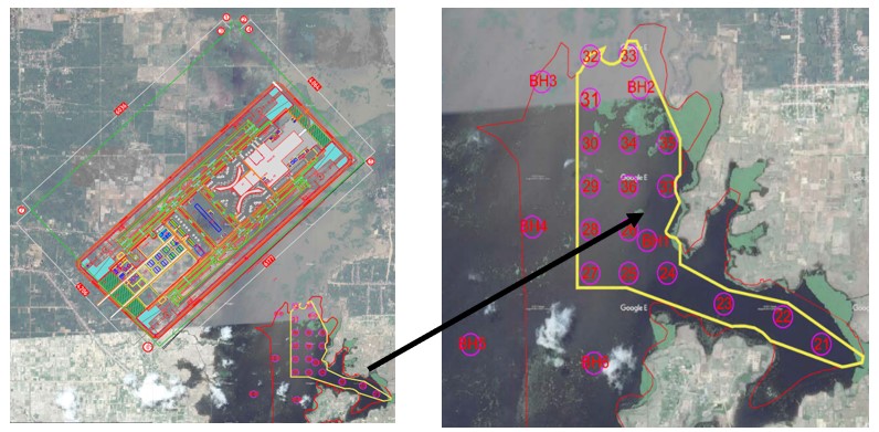
The distance between the airport and proposed excavation site is around 1.4 km. The location of proposed airport and zone of excavation is shown in Figure 1. The sand required for the construction of the new airport was proposed to be extracted from the Boeng Cheung Loung Lake. Therefore, slope stability analysis was undertaken to ensure that the dredging of the sand could be done without failure and excessive movement of the area was checked.
The yellow boundary shows the dredging area for the extraction and this study is focused specifically at this area. Likewise, the requirement of instrumentation for monitoring the movement of the slope in future and the possibility of sand flow was also analyzed.
2. Analysis of boreholes
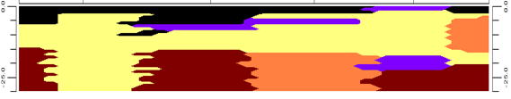
The location and information of different boreholes were used to create a database in Rockworks. Through the database, visualizing the site in 3D, calculating approximate volume and acquiring required section for slope stability analysis were done. Information of 17 boreholes were provided by the client. In Rockworks the studied area is divided into two rectangular areas. The lithology of each borehole was imported in the data base of Rockworks and for ease in visualization, 3D multi-log view was generated as shown in Figure 2.
Four boreholes, namely BH 21 to BH 24 comprised area B, while area A consisted of boreholes, BH 24 to BH 37 as shown in Figure 3. From the boreholes, it was found that mainly 4 types of soil and Sandstone is present at the site. According to USCS, the soil of the excavation site is classified as Silt with high plasticity (MH), Sandy clay (SC), Clayey sand (SC), Fine Sand (SM).


2.1 Volume calculation
The aim of the excavation is to extract the sand required for Vacuum consolidation during the construction of an international airport at Phnom Penh, Cambodia. The clean sand (SM) and other soils including clayey sand (SC) and even sandy clay (CL) through a thorough washup can be used for VCM. It was found that the most predominant soil at the excavation area is the clayey sand, followed by sand and sandy clay respectively. The most desirable soil that can be used without much treatment will be the sand which is found in the leftmost part of the area A and more at area B.
If it’s possible further investigation with a borehole at the left side of the excavation area can be done to ascertain it and the quantity of this soil may be increased accordingly. The client plans to use clayey sand too after washing it up. They are abundantly found in both of the areas and the sandy clay which requires the most cleaning (if appropriate to use) is found sparsely.
RockWorks15 was used to generate different sections of the study area which were then imported in AutoCAD to calculate the volume of materials (manually) that can be acquired at excavation slope of 1:3 and 1:4, and are shown in Table 1 and Table 2 respectively.
Table 1. Approximate volume of soil from the study area (1:3)
| Soil | Dredging Area, A | Dredging Area, B | Total Volume (m3) |
| Silt with high plasticity (MH) | 4,594,975 | 1,578,925 | 6,173,900 |
| Clayey Sand (SC) | 11,447,374 | 5,465,764 | 16,913,138 |
| Sand (SM) | 2,489,070 | 3,027,075 | 5,516,145 |
| Sandstone | 3,781,091 | 1,599,040 | 5,380,131 |
| Sandy Clay (CL) | 681,000 | 1,847,010 | 2,528,010 |
Table 2. Approximate volume of soil from the study area (1:4)
| Soil | Dredging Area, A | Dredging Area, B | Total Volume (m3) |
| Silt with high plasticity (MH) | 4,557,031 | 1,564,725 | 6,121,756 |
| Clayey Sand (SC) | 10,559,335 | 4,893,390 | 15,452,725 |
| Sand (SM) | 2,117,850 | 2,577,122 | 4,694,972 |
| Sandstone | 3,247,610 | 994,800 | 4,242,410 |
| Sandy Clay (CL) | 621,810 | 1,765,775 | 2,387,585 |
2.2 Investigation of different section
From the information of boreholes provided, database was created in Rockworks 15. Investigation of different section of the study area was then carried out to determine the most desriable as well as undesirable area for the excavation. Three sections were considered for analysis as shown in Figure 4.

BH 32 – BH 31 – BH 30 – BH 29 – BH 28 – BH 27 comprised Section 1 and is at the leftmost side of the study area. BH 33 – BH 34 – BH 36 – BH 26 – BH 25 comprised Section 2 and it lies at the middle portion of the study area A. The third section (Section 3) is extended from the rightmost portion of study area A to B and consists of boreholes namely, BH 35 – BH 37 – BH 24 – BH 23 – BH 22 – BH 21.

The thickness of soil layer for silt with high plasticity soil (MH) is low for this section (within 5m) and hence is considered relatively safe from slope stability considerations. The area under BH 30 is the most suitable area to get high amount of sand. Throughout the other section, there is abundant amount of clayey sand.

The thickness of the undesired soil layer, silt with high plasticity (MH), increases as we proceed from BH 33 to BH 25. The thickness of MH is the most at BH25 area (10 meters) and hence it can complicate the excavation process. Also, the amount of desirable soil is quite less for both BH 26 and BH 25 as only a small portion of clayey sand is sandwiched between MH and sandstone. In this section the most suitable area is under BH 34 as abundant clayey sand as well as sand is found under this zone.
This section is extended from study area A (BH 37- BH 35 – BH 24) to study area B (BH 21 -BH 22 – BH23 – BH24). BH 24 is a bridge between area A and area B and the area under BH 24 is the most undesirable section as there is a presence of thick layer of high plasticity silt (MH) (more than 10 meters) as well as sandstone is present from 15 meters to 30 meters, hence the amount of usable soil is very less (considering SC to be usable). In area B, the most usable area is under BH23 where the thickness of MH is low and sandstone is absent. There is also a presence of sand (SM) at deep depth (around 15 m) and clayey sand (SC) at shallow depth.
3. NUMERICAL MODELING
The numerical model of Boeng Cheung Loung Lake was conducted using SLOPE/W and PLAXIS 2019. All the parameters used in numerical analysis was used from the result of soil investigation report conducted on December, 2019. The slope stability analysis helps determine the soil mechanical properties, the shape and the location of the possible failure surface.
Slope stability analysis was performed to determine the safety factors of the lake during and after the excavation using limit equilibrium method Morgenstern Price Method (Zhu, Lee, Qian, Zou, & Sun, 2001). The limit equilibrium method (LEM) (Duncan, Wright, & Brandon, 2014) is the most common method of analysis because the calculation method is straightforward with accuracy comparable to rigorous methods like finite element and finite difference approach. This analysis was carried out for various cases to design the excavation slope at multiple locations. The locations used are based on the soil investigation report conducted on December, 2019.
a) Worst Case Scenario:
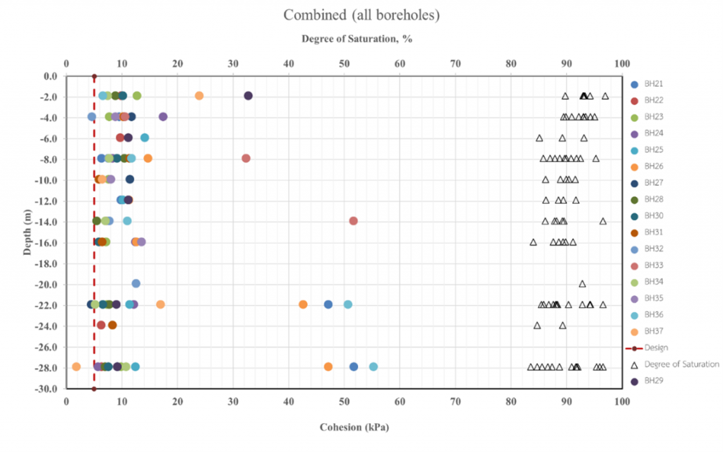
Analysis was preliminary conducted for the worst-case scenario to determine the slope of excavation. This analysis helps in determining the slope of excavation for when the strength parameters are minimum. Strength parameters used in this analysis was taken from the results of each borehole investigation. The strength parameters were determined from quick direct shear test. The plot between cohesion and degree of saturation for various boreholes is shown in Figure 8. From this plot, the value of cohesion was selected as 5 kPa for preliminary analysis as shown in Figure 8. The degree of saturation plotted are in the range of 83.51% – 96.92%.
Similarly, the relationship between friction angle and depth for samples obtained from various boreholes is shown in Figure 9. The result shows that the friction angle increases with depth and hence 3 values of friction angle was used for the analysis and is shown in Table 3. Furthermore, the relationship between unit weight and depth of samples obtained from various boreholes were also plotted and is shown in Figure 10. The result shows that the unit weight increases with depth and hence has been categorized into 3 values of unit weight. The parameter used in the analysis is shown in Table 3.

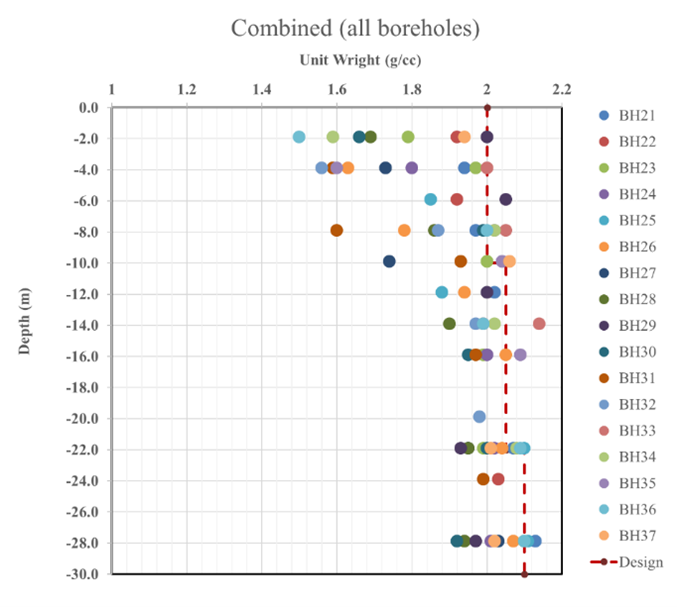
Figure 10 . Variation of Unit weight with depth for samples for various boreholes
Table 3. Material Property used for the worst case scenario
| Material Properties Used | |||
| Cohesion (kPa) | Friction Angle (φ) | Unit Weight (kN/m3) | |
| First Layer | 5 | 8 | 20 |
| Second Layer | 5 | 20 | 20.5 |
| Third Layer | 5 | 28 | 21 |
The result obtained from site investigation was used in numerical analysis using SLOPE/W. The model used four slopes (1:1, 1:2, 1:3 and 1:4) for the preliminary slope stability analysis. From the site inspection and discussion with client representatives, it was determined that the water in Boeng Cheung Lake is always full and hence the analysis was based on lake with full ponding throughout the year. The analysis was not conducted for the case with drawdown of water. The summary of Slope stability analysis for various slopes (1:1, 1:2, 1:3 and 1:4) with ponding is presented in Table 4.
Table 4. Factor of Safety for Various Slopes for worst case scenario
| Case | Slope | Water | FoS |
| Case 1 | 1:1 | With Ponding | 0.64 |
| Case 2 | 1:2 | With Ponding | 0.87 |
| Case 3 | 1:3 | With Ponding | 1.12 |
| Case 4 | 1:4 | With Ponding | 1.36 |
From the preliminary analysis, it has been found out that the slope is not stable at 1:1 and 1:2 and it is highly not recommended to use these slopes during the excavation work. Slope of 1:3 and 1:4 have factor of safety greater than unity, and hence detail analysis was further carried out at each borehole locations and section to select the suitable slope for the excavation.
b) Analysis with soil layers from each borehole
From preliminary analysis, the design slope for the excavation of Boeng Cheung Lake has been identified as 1:3 or 1:4. Detail analysis was further conducted at each bore hole location to determine its safety factor. Various materials found from soil investigation result was separately categorized to identify the variance in material property of each soil type. The plot between cohesion and friction angle was obtained for various soil samples as shown in Figure 11. The material property of each soil type was identified from the plot and was used in numerical analysis. The material property used for the analysis is as shown in Table 5.

Table 5. Material Properties used in Numerical Analysis
| Soil Types | Cohesion (kPa) | Friction Angle (φ) | Unit Weight (kN/m3) |
| CL | 12.74 | 10.17 | 20.7 |
| MH | 4.61 | 3.55 | 16.6 |
| ML | 8.82 | 8.5 | 17.4 |
| SC | 1.84 | 20.37 | 20.5 |
| SM | 4.51 | 24.83 | 20.9 |
| Sandstone (CL) | 45.63 | 18.47 | 21.4 |
Cross section was plotted at location where soil investigation work was carried out for slope 1:3 and 1:4. The result is summarized in Table 6 . The allowable factor of safety used for this analysis is 1.3 and the cases that are below 1.3 are highlighted red.
Table 6. Factor of Safety for slope 1:3 and 1:4 at various borehole locations
| S.N | Borehole no. | Factor of Safety | |
| 1:3 | 1:4 | ||
| 1 | BH 21 | 1.55 | 2.91 |
| 2 | BH 22 | 1.30 | 1.61 |
| 3 | BH 23 | 1.45 | 1.85 |
| 4 | BH 24 | 1.32 | 1.71 |
| 5 | BH 25 | 1.06 | 1.26 |
| 6 | BH 26 | 1.06 | 1.26 |
| 7 | BH 27 | 1.31 | 1.81 |
| 8 | BH 28 | 1.37 | 1.77 |
| 9 | BH 29 | 1.34 | 1.76 |
| 10 | BH 30 | 1.70 | 1.96 |
| 11 | BH 31 | 1.34 | 1.73 |
| 12 | BH 32 | 1.38 | 1.80 |
| 13 | BH 33 | 1.43 | 1.82 |
| 14 | BH 34 | 1.38 | 1.78 |
| 15 | BH 35 | 1.55 | 2.00 |
| 16 | BH 36 | 1.29 | 1.68 |
| 17 | BH 37 | 1.29 | 1.67 |
Finite Element Modelling:
PLAXIS (Brinkgreve et al., 2016) is a finite element program for geotechnical applications in which soil models are used to simulate the soil behaviour. It’s implementation consists of three stages, known as input stage, calculation stage and postprocessing stage. Input stage contains model design,assigning the material parameters, boundary conditions, loading and meshing.
To determine the factor of safety using the FEM, repeated analyses are performed, each time reducing the strength of the soil by a slightly greater factor, until an unstable condition results. This unstable condition is evidenced by failure of the solution to converge. The term strength reduction factor (SRF) (Dawson, Roth, & Drescher, 1999) is used rather than factor of safety, FS, although SRF and FS are the same in principal. Like the factor of safety, the strength reduction factor is the factor by which the shear strength must be divided so that the reduced strength is in barely stable equilibrium with the shear stresses. All borehole profiles were analyzed in FEM and the material properties used in the analysis for each borehole. E modulus of the soil were chosen based on the correlation with SPT otained from the test report.
With the material properties as input for various soil layers, finite element analysis was carried out for excavation slope of 1:3 and 1:4 to determine the displacement in the horizontal direction and factor of safety was calculated based on c-phi reduction method. The results of the analysis are tabulated in Table 7. Safety factor obtained from both LEM and FEM yield identical results. The factor safety of BH25 and BH26 for both 1:3 and 1:4 is less than 1.3 and requires preventive measures during excavation. It is recommended to avoid these boreholes and area to their vicinity, if possible. Likewise, it is also recommended to maintain the slope of 1:4 for locations with borehole BH26 and BH37.
Table 7. Displacement and FS results from FEM
| S.N | Borehole no. | Displacement (ux), meters | Displacement (uy), meters | Factor of Safety | |||
| 1:4 | 1:3 | 1:4 | 1:3 | 1:4 | 1:3 | ||
| 1 | BH 21 | 0.0863 | 0.0971 | 0.1058 | 0.1068 | 2.272 | 1.749 |
| 2 | BH 22 | 0.1083 | 0.1417 | 0.2334 | 0.2514 | 2.108 | 1.774 |
| 3 | BH 23 | 0.1213 | 0.1332 | 0.2982 | 0.2981 | 2.153 | 1.684 |
| 4 | BH 24 | 0.07306 | 0.08305 | 0.1871 | 0.1865 | 1.726 | 1.491 |
| 5 | BH 25 | 0.0622 | 0.09232 | 0.1503 | 0.1495 | 1.254 | 1.052 |
| 6 | BH 26 | 0.058 | 0.06963 | 0.1091 | 0.1093 | 1.244 | 1.057 |
| 7 | BH 27 | 0.2307 | 0.2535 | 0.05181 | 0.06297 | 2.273 | 1.895 |
| 8 | BH 28 | 0.1481 | 0.158 | 0.3634 | 0.321 | 1.691 | 1.296 |
| 9 | BH 29 | 0.117 | 0.1303 | 0.3093 | 0.3076 | 2.157 | 1.705 |
| 10 | BH 30 | 0.08375 | 0.09679 | 0.2223 | 0.2214 | 2.152 | 1.641 |
| 11 | BH 31 | 0.06593 | 0.07688 | 0.154 | 0.1524 | 1.685 | 1.321 |
| 12 | BH 32 | 0.06485 | 0.07654 | 0.1539 | 0.1528 | 1.711 | 1.324 |
| 13 | BH 33 | 0.04589 | 0.05064 | 0.1112 | 0.1111 | 2.254 | 1.823 |
| 14 | BH 34 | 0.04702 | 0.05162 | 0.1128 | 0.113 | 2.18 | 1.722 |
| 15 | BH 35 | 0.03979 | 0.04669 | 0.1041 | 0.1038 | 1.772 | 1.496 |
| 16 | BH 36 | 0.1006 | 0.08242 | 0.1574 | 0.1632 | 2.671 | 1.237 |
| 17 | BH 37 | 0.1055 | 0.09905 | 0.1601 | 0.1998 | 2.509 | 1.239 |
Furthermore, displacement of the slope at various locations was obtained for BH25 and BH27 for excavation slope of 1:3 and 1:4. BH25 was chosen in this analysis as this location has the minimum factor of safety and has the maximum chance of failure. Likewise, BH27 was found to have the maximum displacement among all borehole locations and hence a detailed analysis was conducted in this section. The graph plotted between total displacement and depth shows the movement of sand after the completion of excavation work. Depth in the analysis is measured from the bottom to the top.


From the analysis, the maximum distance that will be affected by the excavation work was found to be 300m. The displacement at 300m for BH 27 was 1.25mm and 1.45mm for slope 1:4 and 1:3 respectively. So, the possible affected area by the excavation shall be not more than 350m from the point of excavation and hence it is recommended to maintain the buffer distance of 350m. It is also advised not to place any heavy equipment in the buffer zone.
- Probabilistic analysis:
Engineering data on soil or rock mass properties are usually scattered and hence simple probabilistic methods are useful in summarizing the scatterings to get a better understanding of the data – and of the corresponding uncertainties associated with engineering performance. The concept of probability (Griffiths & Fenton, 2007) with various geotechnical uncertainties was used for determination of probability of failure. Coefficient of variation was used to determine the variation of soil properties (i.e. cohesion, friction angle and unit weight). The coefficient of variation was separately determined for various material obtained from site investigation and was compared with the available variation values from the literature. Coefficient of variation is the ratio of standard deviation to the mean. The result of coefficient of variation for different material is shown in Table 8.
Table 8. Coefficient of Variation for different soil properties
| Soil Group | Mean | Standard Deviation | Coefficient of Variation (%) | ||||||
| Cohesion (kPa) | Angle of Friction (o) | Unit Weight (g/cc) | Cohesion (kPa) | Angle of Friction (o) | Unit Weight (g/cc) | Cohesion (kPa) | Angle of Friction (o) | Unit Weight (g/cc) | |
| MH | 8.70 | 9.06 | 1.59 | 2.31 | 2.29 | 0.05 | 26.53 | 25.24 | 2.98 |
| ML | 10.68 | 8.65 | 1.72 | 1.62 | 0.23 | 0.03 | 15.17 | 2.68 | 1.54 |
| CL | 21.14 | 12.94 | 1.89 | 8.59 | 3.27 | 0.11 | 40.63 | 25.31 | 5.80 |
| SC | 11.18 | 26.67 | 2.00 | 2.98 | 2.44 | 0.07 | 26.66 | 9.16 | 3.41 |
| SM | 7.79 | 30.27 | 1.99 | 1.82 | 2.38 | 0.05 | 23.32 | 7.87 | 2.62 |
| Sandstone | 49.46 | 19.27 | 2.09 | 4.14 | 0.59 | 0.04 | 8.36 | 3.08 | 1.69 |
The probability of failure was estimated for slope 1:3 and 1:4 at the locations where soil investigation was carried out. The probability of failure was estimated based on quality measure of likelihood and probability proposed by (Santamarina, Altschaeffl, & Chameau, 1992). The factor of safety estimated from mean value of strength parameters and probability of failure for all borehole location is presented in Table 9.
Table 9: Probability of failure for slope 1:3 and 1:4 at various borehole locations
| S.No. | Borehole | Slope | Factor of Safety | Probability of Failure (%) | Remarks |
| 1 | BH21 | 1:3 | 2.50 | 0.00 | |
| 1:4 | 3.15 | 0.00 | |||
| 2 | BH22 | 1:3 | 2.01 | 0.00 | |
| 1:4 | 2.48 | 0.00 | |||
| 3 | BH23 | 1:3 | 2.30 | 0.00 | |
| 1:4 | 2.95 | 0.00 | |||
| 4 | BH24 | 1:3 | 2.29 | 0.00 | |
| 1:4 | 2.98 | 0.00 | |||
| 5 | BH25 | 1:3 | 2.23 | 0.18 | Acceptable |
| 1:4 | 2.72 | 0.10 | Acceptable | ||
| 6 | BH26 | 1:3 | 2.23 | 0.30 | Acceptable |
| 1:4 | 2.17 | 0.10 | Acceptable | ||
| 7 | BH27 | 1:3 | 2.54 | 1.00 | Possible |
| 1:4 | 3.05 | 0.20 | Acceptable | ||
| 8 | BH28 | 1:3 | 2.35 | 0.00 | |
| 1:4 | 3.09 | 0.00 | |||
| 9 | BH29 | 1:3 | 2.36 | 0.00 | |
| 1:4 | 3.06 | 0.00 | |||
| 10 | BH30 | 1:3 | 2.38 | 0.00 | |
| 1:4 | 3.15 | 0.00 | |||
| 11 | BH31 | 1:3 | 2.32 | 0.00 | |
| 1:4 | 3.03 | 0.00 | |||
| 12 | BH32 | 1:3 | 2.45 | 0.00 | |
| 1:4 | 3.14 | 0.00 | |||
| 13 | BH33 | 1:3 | 2.52 | 0.00 | |
| 1:4 | 3.25 | 0.00 | |||
| 14 | BH34 | 1:3 | 2.40 | 0.00 | |
| 1:4 | 3.16 | 0.00 | |||
| 15 | BH35 | 1:3 | 3.00 | 0.00 | |
| 1:4 | 3.82 | 0.00 | |||
| 16 | BH36 | 1:3 | 2.25 | 0.00 | |
| 1:4 | 2.94 | 0.00 | |||
| 17 | BH37 | 1:3 | 2.24 | 0.00 | |
| 1:4 | 2.94 | 0.00 |
Borehole BH25, BH26 and BH27 has the possibility of failure and requires propoer attention during the excavation work. It has been determined that the slope 1:3 is acceptable for all boreholes except for BH25 and BH26.
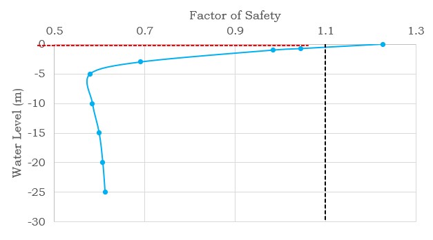
All the previous analysis has been conducted with an assumption that the water in lake will not be affected by the excavation work and will remain full throughout the year. But the analysis was also conducted by numerical modelling to determine the minimum water level that is permissible after the excavation work. The analysis was conducted for BH25 with slope 1:4 and BH37 for slope 1:4 and 1:3. It has already been discussed in previous sections regarding BH25 and need of avoiding this section during the excavation work. This analysis presents the impact at this location with removal of water. Similarly, BH37 was used in this analysis because this location has the minimum permissible factor of safety along the borehole location tested. It has been determined that, if excavation is continued in BH25 with slope 1:4, the water level should never be reduced. Similarly, it is not recommended to excavate the lake with excavation slope of 1:3 as factor of safety will be less than 1.3 even when the lake is completely filled (Figure 16). Likewise, for the excavation with slope 1:4, the maximum permissible reduction in water level is 5m and it is advised to consider this result during the excavation of Boeng Cheung Lake.
It is recommended to closely monitor the slope if the factor of safety is less than 1.3 after reduction of water level. It is required to investigate the source of water nearby that might be required if the water level reduces again. Likewise, if the factor of safety is less than 1.1, the water level should be filled in the lake and people nearby should be alarmed regarding the impact that might occur in coming days. If the factor safety reaches 1.0, the nearby area should be evacuated as soon as possible for the safety of people living nearby. It was informed by the client representatives that the water level will be constant throughout the year, this analysis was conducted to determine maximum permissible reduction in water level. If any unforeseen circumstances lead to the reduction in water level, there might be the necessity of further site investigation and further analysis

5. Instrumentation
There are specific instruments that geotechnical engineers install for the purpose of monitoring the behavior of geotechnical structures during its construction and operation. Its purpose is multi-fold, serving both investigative and monitoring functions that are in part a necessity to ensure the economic feasibility of the project operations and in part due diligence to ensure safe operations. Investigative functions includes providing an understanding of the ground conditions for prefeasibility and design purposes, providing input values for design calculations, and checking for changing ground conditions as workings progress to greater depths. Installation of instruments for monitoring the behavior of slope after the excavation is recommended for Boeng Cheung Lake.

On the basis of site investigation and FEM analysis, it is recommended to install the inclinometer (Stark & Choi, 2008) every 500m and monitor constantly. The inclinometer should be placed close to the excavation slope and location should be accessible for monitoring the results. It is recommended to install the manual inclinometer as the probability of failure of the slope is low and impact due to its failure is not severe. The preliminary location of inclinometer is shown in Figure 15. It is recommended to install 14 inclinometers. The proposed number and location of the inclinometer is based on the preliminary analysis and its final number and location should be based on geological topography of the location. Likewise, it is also recommended to install the permanent benchmark in nearby location. The benchmark should be used to record Easting, Northing and Elevation at the location where inclinometers are installed. It also helps in observing the movement and settlement of the slope, if any.
6. Dredeging mechanism and recommendation
Dredging is an excavation activity usually carried out at least partly underwater, in shallow seas or fresh water areas with the purpose of gathering up bottom sediments and disposing them at different location (Bray, 2008). The operation is undertaken by special floating plant, known as dredger. A dredgers can dig, transport and dump a certain amount of underwater laying soil in a certain time and can dig hydraulically or mechanically. Hydraulic digging make use of the erosive working of a water flow. The flow will erode the sand bed and forms a sand-water mixture before it enters the suction pipe. Hydraulic digging is mostly done with special water jets mostly in cohesionless soils such as silt, sand and gravel. Mechanical dredgers come in a variety of forms, each involving the use of grab or bucket to loosen the in-situ material and raise and transport it to the surface. The choice of the dredger for executing a dredging operation depends on conditions such as the accessibility to the site, weather and wave conditions, anchoring conditions, required accuracy and so on. Cutter suction dredger and Jet suction dredger are the two possible dredging equipment that can be used for the excavation.
To determine the type of dredger for excavation of Boeng Cheung Lake, consultation with the manufacturers of both cutting suction dredger and jet suction dredger was done. It was found that the clay layer needs to be removed first to extract the underlying sand layer. The general excavation depth of cutting suction dredger is 20m and if this remains true, it is highly advised to extend the excavation area and conduct additional site investigation work to obtain the same amount of sand. Since, the manufacturer has agreed to modify the dredger as per the requirement of the client (30 m depth) , the excavation work can be executed with cutter suction dredger. Likewise, we also know that the lake consists of clayey sand and sandy clay, and for using it, it is recommended to use additional sand washing machine.
If we are looking to just suck the sand without digging, then jet suction may be used but it can take overburden of around 3m only, so for the section with clay deposit greater than 3m, it might not be usable. Theoretically, the jet suction dredger can only be used for the extraction of cohesionless material (pure sand) and since the lake consists of sandy clay and clayey sand, the use of jet suction dredger is limited.
The presence of fine content and plasticity index in clayey sand is shown in Table 0. The soil contains high amount of fine content material and has high plasticity index. This soil cannot be extracted using jet suction dredger. Hence, based on the site investigation report, it has been observed that the jet suction dredger can only be used at certain sections.
Table 10: Plasticity Index and Fine Content for Various Soil Property
| S.No. | Soil Property | Plasticity Index (PI) % | Fine Content (FC) % |
| 1 | Clay (MH) | 19.9 – 34.6 | 76.8 -93.3 |
| 2 | Clayey Sand (CL) | 16 – 27.8 | 50.5 – 83.2 |
| 3 | Sandy Clay (SC) | 7.2 – 12.8 | 26.7 – 44.3 |
| 4 | Pure Sand (SM) | – | 13.1 – 33.7 |
Therefore, cutting suction dredger is recommended for the excavation of Boeng Cheung Loung. It can be used for the excavation of clay layer and extract the sand. The clay should be properly relocated before extraction of sandy materials. The jet suction dredger as mentioned before can be used only at some locations where the depth of clay layer is less than 3m. It is also recommended to consult the manufacturer in detail about the possible equipment to be used since the capacity of the dredging equipment to meet our demand greatly depends upon the specifications of different models existing in the market. Nonetheless, whichever equipment is used, settlement will occur upon extraction of the sand which by the analysis shows not to be affecting area greater than 350 m.
7. Conclusion
Conceptual design of for the excavation of Boeng Cheung Loung Lake is proposed in this report. The analysis was based on the results from Site Investigation, LEM and FEM analysis. The conclusion and recommendation has been listed below:
- It has been found that the location with BH28, BH29 and BH30 have sand layer in shallow layer and it is recommended to start the excavation from this section.
- The amount of fine sand is found mostly in areas under BH 30, BH 29 and BH 28. Under BH 30, the sand is found at a depth nearly of 5 m whereas for BH 29 and BH 28 they are found at depths of 20 m. The red zone BH 26 – BH 25 and BH 24 consists of thick deposits of high plastic silt (MH) and is underlain by sandstone too. It is recommended to conduct further soil investigation (3 bore hole investigation) proximity to BH 30 to determine the soil property in this region. There is a high possibility that this region might have clean sand. The detail description of the borehole investigation result is as shown in Figure .

- Soil Investigation at BH21, BH22 and BH23 shows the presence of pure sand layer. BH 23 and BH 25 consists of sand (SM) and are found in deeper (17 m) and shallow depths (5 m) respectively. However, in area B the stretch available for the excavation is not enough. To utilize the material of this section, its width needs to be increased and excavation should be carried out accordingly.
- The factor of safety at location BH25 and BH26 is very low and if possible, it is recommended to avoid this area. If avoiding is not possible then slope of 1:4 (Figure 16) must be strictly used in this region with constant monitoring of the slope whereas in other boreholes 1:3 is satisfactory. If not, there is a possibility that this slope might fail during or after excavation.

- From FEM results we can see that the high displacement in x-direction occurs for BH 27 and BH 28, ranging from 21 -25 cm, being more for slope at 1:3 than at 1:4. This is because of the low SPT values reported and the E modulus shall correspondingly decrease. Similarly, BH 23 also reported for lower SPT values throughout its depth (less than 10) which resulted in relatively larger displacement (27 cm for 1:3 slope, 12 cm for 1:4 slope). Other BH to consider are BH 36 and 37 with displacements ranging from 12 to 14 cm.
- FEM analysis exhibited that the maximum distance that will be affected by the excavation work is 300m. The displacement at 300m for BH 27 was found to be around 1.25mm and 1.45mm for slope 1:4 and 1:3 respectively. So, the possible affected area by the excavation shall be not more than 350m from the point of excavation and hence it is recommended to maintain the buffer distance of 350m. It is also advised not to place any heavy equipment in the buffer zone.
- For the excavation with slope 1:3, the maximum permissible reduction in water level is 4m. Likewise, for the excavation with slope 1:4, the maximum permissible reduction in water level is 6.5m.
- The result from probabilistic analysis shows the possibility of failure at BH25, BH27 and BH28. So, it recommended to maintain the slope 1:4 at these locations and should be constantly monitored during the excavation period.
- The quantity of clayey sand is high in Boeng Cheung Lake and it’s highly recommended to clean the clay before using it for the construction of airport.
References
Bray, R. N. (2008). Environmental aspects of dredging: CRC Press.
Brinkgreve, R., Kumarswamy, S., Swolfs, W., Waterman, D., Chesaru, A., & Bonnier, P. (2016). PLAXIS 2016. PLAXIS bv, the Netherlands.
Dawson, E., Roth, W., & Drescher, A. (1999). Slope stability analysis by strength reduction. Geotechnique, 49(6), 835-840.
Duncan, J. M., Wright, S. G., & Brandon, T. L. (2014). Soil strength and slope stability: John Wiley & Sons.
Griffiths, D. V., & Fenton, G. A. (2007). Probabilistic methods in geotechnical engineering (Vol. 491): Springer Science & Business Media.
Santamarina, J., Altschaeffl, A., & Chameau, J. (1992). Reliability of slopes: incorporating qualitative information (abridgment). Transportation Research Record(1343).
Stark, T. D., & Choi, H. (2008). Slope inclinometers for landslides. Landslides, 5(3), 339-350.
Zhu, D., Lee, C., Qian, Q., Zou, Z., & Sun, F. (2001). A new procedure for computing the factor of safety using the Morgenstern-Price method. Canadian geotechnical journal, 38(4), 882-888.